- 您现在的位置:买卖IC网 > Sheet目录346 > NCV7517BFTR2G (ON Semiconductor)IC PREDRIVER HEX LOW SIDE 32LQFP
NCV7517B
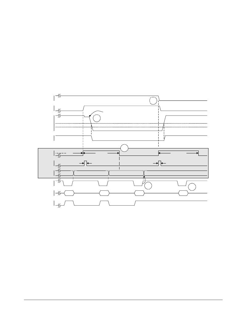
Shorted Load Recovery
Figure 19 is a continuation of Figure 18. IN X is high
when the auto ? retry timer ends. GAT X goes high and the
blanking and filter timers are started. The fault is removed
before the blanking timer ends, and DRN X starts to fall. As
DRN X passes through the V OL threshold at “A”, the STAB
flag is set. DRN X continues to fall and settles below the
FLTREF threshold.
An SPI frame is sent during the blanking time and returns
data indicating a “shorted load” fault. Although the fault is
removed, updates to the fault latches are suppressed while
a blanking or filter timer is active. The same fault is
captured again and FLTB is set when CSB goes high. At
“B” the blanking time ends and the channel’s fault bits will
indicate “no fault” but because the latched data has not yet
been read, the data remains unchanged.
The SPI frame sent after the blanking time ends returns
a “shorted load” fault because the previous frame occurred
during the blanking time. Since the channel’s fault bits
indicate “no fault”, FLTB is reset and the fault latch is
updated at “C” when CSB goes high. If another SPI frame
is sent before “D”, the returned data will indicate “no
fault”.
The channel is commanded off at “D”. GAT X goes low
and the timers are started. DRN X starts to rise and the STAB
flag is reset as DRN X passes through the V OL threshold.
The SPI frame sent at “E” returns data indicating “no
fault”.
INx
GATx
1
0
1
0
FAULT REMOVED
D
VLOAD
VOL
FLTREF
0
A
STAB
1
0
BLANK
TIMER
FILTER
TIMER
FAULT
LATCH
CSB
1
0
1
0
1
0
1
0
11
t FR
11
t FF
t BL(ON)
B
11
INTERNAL
SIGNALS
C
t FF
t BL(OFF)
00
E
SO
1
0
11
11
11
00
FLTB
1
0
Figure 19. Shorted Load Recovery
http://onsemi.com
19
发布紧急采购,3分钟左右您将得到回复。
相关PDF资料
NCV8855BMNR2GEVB
BOARD EVALUATION NCV8855 ASIC
NCV8871BSTGEVB
BOARD EVAL NCV8871BST BOOST CTLR
NHC-14150
VALULINE 8" X 8.5" X 1.75"
NHC-14151
VALULINE 8" X 17" X 1.75"
NHC-14152
VALULINE 13" X 17" X 1.75"
NHC-14153
VALULINE 8" X 8.5" X 3.5"
NHC-14154
VALULINE 8" X 17" X 3.5"
NHC-14155
VALULINE 13" X 17" X 3.5"
相关代理商/技术参数
NCV7517FTG
功能描述:功率驱动器IC HEX LO-SIDE PRE DRIV RoHS:否 制造商:Micrel 产品:MOSFET Gate Drivers 类型:Low Cost High or Low Side MOSFET Driver 上升时间: 下降时间: 电源电压-最大:30 V 电源电压-最小:2.75 V 电源电流: 最大功率耗散: 最大工作温度:+ 85 C 安装风格:SMD/SMT 封装 / 箱体:SOIC-8 封装:Tube
NCV7517FTR2G
功能描述:功率驱动器IC HEX LO-SIDE PRE DRIV RoHS:否 制造商:Micrel 产品:MOSFET Gate Drivers 类型:Low Cost High or Low Side MOSFET Driver 上升时间: 下降时间: 电源电压-最大:30 V 电源电压-最小:2.75 V 电源电流: 最大功率耗散: 最大工作温度:+ 85 C 安装风格:SMD/SMT 封装 / 箱体:SOIC-8 封装:Tube
NCV7518
制造商:ONSEMI 制造商全称:ON Semiconductor 功能描述:FLEXMOS Hex Lowa??side MOSFET Prea??driver
NCV7518MWTXG
制造商:ONSEMI 制造商全称:ON Semiconductor 功能描述:FLEXMOS Hex Lowa??side MOSFET Prea??driver
NCV7601
制造商:ONSEMI 制造商全称:ON Semiconductor 功能描述:Quad Driver
NCV7601/D
制造商:未知厂家 制造商全称:未知厂家 功能描述:Quad Driver
NCV7601_06
制造商:ONSEMI 制造商全称:ON Semiconductor 功能描述:Quad Driver
NCV7601P
功能描述:功率驱动器IC Quad Driver RoHS:否 制造商:Micrel 产品:MOSFET Gate Drivers 类型:Low Cost High or Low Side MOSFET Driver 上升时间: 下降时间: 电源电压-最大:30 V 电源电压-最小:2.75 V 电源电流: 最大功率耗散: 最大工作温度:+ 85 C 安装风格:SMD/SMT 封装 / 箱体:SOIC-8 封装:Tube
